Control Addressable LED Strips with an ESP32 Using WLED
Build a Wi-Fi controlled addressable RGB LED strip using an ESP32 and the free WLED firmware. In this beginner-friendly project you'll learn how to wire the hardware, install WLED, configure your LEDs, and control hundreds of built-in lighting effects from your phone or web browser.
Control Addressable LED Strips with an ESP32 Using WLED
By the end of this project you'll be able to: - Control your LEDs from your phone, tablet, or computer - Choose from hundreds of built-in lighting effects - Change colors and brightness instantly - Divide your strip into multiple controllable segments - Prepare your project for future smart home integration
| Qty | Part | |----:|------| | 1 | ESP32 Development Board | | 1 | WS2812B Addressable LED Strip (5V) | | 1 | 5V Power Supply sized for your LED count | | 1 | Data-capable USB cable | | 3 | Jumper wires | | Optional | Breadboard | | Optional | 220Ω to 470Ω resistor for the data line | | Optional | 1000µF capacitor for the power input |
Understanding Addressable LEDs
Disconnect external LED-strip power before changing wiring or connecting the ESP32 to your computer. Do not power a long LED strip directly through the ESP32 or its USB connector. Use an external regulated 5V power supply sized appropriately for the strip. Double-check polarity before applying power. Reversing the 5V and ground connections can damage the ESP32 or LED strip.
Wiring the ESP32
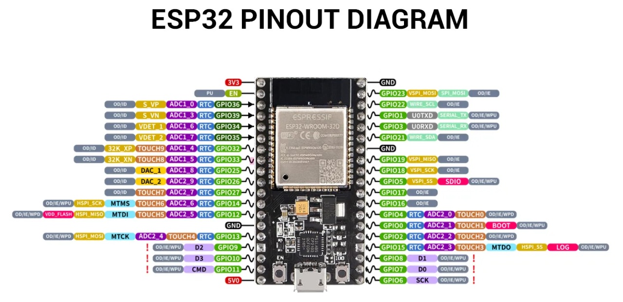
ESP32                 WS2812B LED Strip

5V   ---------------- 5V

GND  ---------------- GND

GPIO16 ------------- DINThe ESP32, LED strip, and external 5V power supply must share a common ground. Without a shared ground, communication may fail completely or produce flickering, random colors, or unreliable operation.
Install WLED on the ESP32
Connect the ESP32 directly to your computer using a data-capable USB cable. A charge-only USB cable can provide power while preventing the installer from detecting the board.
Open the official WLED web installer using the website block below.


On the WLED installer page, select **Install**. Your browser will open a connection window listing available serial or COM ports.
Select the serial or COM port that belongs to your ESP32, then choose **Connect**. If you are unsure which port is correct, disconnect the ESP32, check the list, reconnect it, and select the new port that appears.
Confirm that you want to install WLED and wait while the firmware is written to the ESP32. Do not unplug the board, close the browser tab, or allow the computer to sleep during installation.
Wait for the installer to report that WLED was installed successfully. The ESP32 may restart automatically when installation finishes.
If no serial or COM port appears: - Confirm you are using desktop Chrome or Edge - Try another USB cable - Try another USB port - Avoid an unpowered USB hub - Close Arduino IDE, serial monitors, or other programs using the port - Install the USB-to-serial driver required by your ESP32 board - Disconnect and reconnect the ESP32 Some ESP32 boards may require you to hold the **BOOT** button while the installer begins connecting. Release the button after the connection or flashing process starts.
Connect WLED to Wi-Fi
Use the installer’s **Connect to Wi-Fi** option when it is offered. Enter the name and password for the Wi-Fi network that the ESP32 should use.
If the installer does not offer Wi-Fi setup, open the Wi-Fi settings on your phone or computer and connect to: **WLED-AP** The default password is: **wled1234**
After connecting to WLED-AP, the WLED setup page should open automatically. If it does not open, enter the following address in your browser: http://4.3.2.1
Open **WiFi Settings**, enter your home Wi-Fi network name and password, and select **Save & Connect**. The ESP32 will restart and attempt to join your network.
Most ESP32 boards use 2.4 GHz Wi-Fi. If your router has separate 2.4 GHz and 5 GHz network names, select the 2.4 GHz network for the ESP32.
Reconnect your phone or computer to your normal home Wi-Fi network. Open WLED using the address shown by the installer, the WLED mobile app, your router’s device list, or a local address such as: ```text http://wled.local ``` Local-name support varies by network, so use the ESP32’s assigned IP address if `wled.local` does not open.
If WLED does not appear on your network: - Confirm the Wi-Fi name and password were entered correctly - Confirm the selected network supports 2.4 GHz devices - Move the ESP32 closer to the router - Power-cycle the ESP32 - Look for WLED-AP again - Reconnect to WLED-AP and revisit `http://4.3.2.1`
Configure Your LED Strip
Configure the LED output to match your hardware. **LED Type** Select the LED chipset used by your strip. For this tutorial, use: WS281x The exact wording can vary by WLED version. **Color Order** Many WS2812B strips use: GRB If red and green appear reversed during testing, return to this setting and select the correct color order for your strip. **GPIO** Enter the GPIO connected to the strip’s DIN wire. For this tutorial: 16 **LED Count** Enter the actual number of LEDs connected to this output. Example: 60 **Current Limiter** Set a current limit appropriate for your power supply, especially during initial testing. Save the settings and allow WLED to restart if prompted.
Enter the GPIO number used by the ESP32, not the physical pin number or an unrelated board label. This tutorial uses GPIO16, but your board and wiring may use a different safe output pin.
First Power-On Test
If selecting red produces green, or selecting green produces red, the wiring may be correct but the color-order setting may be wrong. Return to **Config → LED Preferences** and try the correct color order for your strip, such as GRB or RGB.
Power Requirements
Approximate worst-case current estimates

30 LEDs  ≈ 1.8A

60 LEDs  ≈ 3.6A

120 LEDs ≈ 7.2A

These estimates assume up to approximately 60mA per LED at full-brightness white.

Normal effects often use less power, but the power supply and wiring should be selected with adequate capacity.

Always use a properly sized regulated 5V power supply.

Enable WLED's Current Limiter while testing to reduce the risk of overloading the power supply.### LEDs stay off - Verify that the external 5V power supply is on - Confirm that all grounds are connected - Verify that the strip is connected to DIN - Confirm that the configured GPIO matches the wiring - Verify that the LED count is greater than zero - Confirm that the strip voltage matches the power supply ### Random colors or unstable effects - Confirm the ESP32 and LED power supply share ground - Check for loose jumper wires - Shorten the data wire - Add a resistor near the LED strip’s data input - Verify the LED type and color order - Check for inadequate power ### Only the first LED lights This usually indicates a data-path or configuration problem. Check: - DIN connection - Data direction - GPIO setting - LED count - Connections between strip sections - Possible damage to the first LED ### Flickering on long strips - Add a 220Ω to 470Ω resistor to the data line - Add a 1000µF capacitor across 5V and ground near the strip - Use thicker power wires - Inject power at additional points - Consider a proper 5V logic-level shifter for longer data runs
Once you've completed this project, try using WLED for: - Under-desk lighting - TV bias lighting - Gaming room effects - Christmas decorations - Bookshelves - Ceiling accent lighting - 3D printed lamps - Smart signs - Workshop lighting - Holiday displays