Control Addressable LED Strips with an ESP32 Using WLED
Flash WLED onto an ESP32, connect it to Wi-Fi, and configure a WS2812B LED strip using Tutorial Forge Step containers and Copy Boxes.
Flash WLED onto an ESP32, connect it to Wi-Fi, and control a WS2812B LED strip.
Gather your hardware
Many USB cables provide power only. Use a cable that supports data so the WLED installer can detect your ESP32.
Open the WLED installer

Most ESP32 boards work immediately, but some require a USB-to-Serial driver before they appear as a COM port in the WLED installer. Install only the driver that matches the USB chip on your ESP32 board.


Look at the large USB chip next to the USB connector on your ESP32 board. Its part number is usually printed on the chip (for example, CP2102, CH340, CH341, or CH343). Install the matching driver, then reconnect the board and try the WLED installer again. Look at the large USB-to-Serial chip near the USB connector on your ESP32 board. Its part number is usually printed on top of the chip. Common markings include: - CP2102 or CP2104 - CH340 or CH341 - CH343 Install the matching driver, reconnect the ESP32, and then select **Try Again** in the WLED installer.
Install WLED
Do not unplug the ESP32, close the browser tab, or allow the computer to sleep while the firmware is being written.
Connect to the WLED access point
Open the WLED setup page
http://4.3.2.1 Only works while you're connected to the ESP32's temporary Wi-Fi network (WLED-AP) Used for the initial setup before WLED is connected to your home Wi-Fi. This is the default address of WLED's built-in access point. http://wled.local Only works after WLED has successfully joined your home Wi-Fi network. Your phone or computer must also be connected to that same network. It uses mDNS (Bonjour), so support varies by operating system and network. If it doesn't work, use the IP address assigned by your router instead.
Confirm you are still connected to WLED-AP. Temporarily disable mobile data or a VPN if your device keeps switching away from the Wi-Fi connection.
Connect WLED to your home Wi-Fi
Most ESP32 boards use 2.4 GHz Wi-Fi. If your router has separate network names, select the 2.4 GHz network.
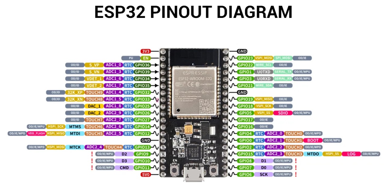
Configure the LED Output
The ESP32, LED strip, and external 5V power supply must share a common ground. Missing common ground can cause flickering, random colors, or no response.
Test the Strip
If selecting red produces green, return to **LED Preferences** and change the color order, such as from GRB to RGB.
This 5V 2A power adapter is suitable for powering the ESP32 and small LED projects. For longer LED strips, such as a full 5-meter strip with 300 LEDs, you will need a much larger regulated 5V power supply. A 2A adapter cannot safely power a strip at full brightness and may cause flickering, unexpected resets, or overheating. Use this adapter for programming, testing, or small LED counts only.

This tutorial uses the **BTF-LIGHTING WS2812B ECO** addressable RGB LED strip. ### Specifications - Individually addressable WS2812B LEDs - 5V operation - 300 LEDs total - 5 meters (16.4 ft) - 60 LEDs per meter - Black flexible PCB - Compatible with WLED and ESP32 - Cuttable at marked locations - Supports millions of colors and hundreds of built-in WLED effects ### Why This Strip? The WS2812B is one of the most popular LED strips supported by WLED. Each LED contains its own controller, allowing every LED to display a different color independently. This makes it possible to create effects such as: - 🌈 Rainbow animations - 🔥 Fire effects - 💧 Color wipes - 🎄 Holiday lighting - 💡 Accent lighting - 🎮 Gaming room effects ### Powering This Project For this tutorial we're using a **5V 2A USB power adapter**. Although the full 300-LED strip is capable of drawing much more current at maximum brightness, it works well for learning and testing when WLED's **Current Limiter** is enabled. **Recommended starting value:** - Current Limiter: **3000 mA** Keeping the current limit at **3000 mA or lower** helps prevent overloading a small power supply while still allowing you to experiment with colors and effects safely. If you later want to run the strip at full brightness or display solid white across all 300 LEDs, upgrade to a larger regulated 5V power supply with sufficient current capacity.
This tutorial uses the **hiBCTR ESP32-DevKitC-32** development board. The ESP32 is a powerful, low-cost microcontroller from Espressif that includes built-in **2.4 GHz Wi-Fi** and **Bluetooth**, making it an excellent choice for smart lighting, home automation, IoT projects, and WLED installations. :contentReference[oaicite:0]{index=0} ### Why It's Great for WLED - ✅ Fully supported by WLED - ✅ Built-in Wi-Fi for wireless control - ✅ Dual-core processor for smooth animations - ✅ USB Type-C connector for power and programming - ✅ Plenty of GPIO pins for LEDs, sensors, and accessories - ✅ Compatible with Arduino IDE, PlatformIO, ESP-IDF, and the WLED Web Installer ### USB-to-UART Bridge This development board uses a **Silicon Labs CP2102 USB-to-UART bridge**. The CP2102 converts USB communication from your computer into the serial interface used to program the ESP32. Benefits include: - Reliable USB communication - Automatic programming and reset support - Broad Windows, macOS, and Linux compatibility - Supported directly by the WLED browser installer If your computer does not recognize the board or no COM port appears, install the **Silicon Labs CP210x USB Driver** before continuing. :contentReference[oaicite:1]{index=1} ### Perfect for Learning This board is ideal for beginners because it works with thousands of ESP32 tutorials and projects, including: - WLED LED controllers - Home Assistant integrations - Web servers - MQTT projects - Sensors and automation - Bluetooth applications - IoT dashboards - DIY smart home devices Once you've completed this tutorial, the same ESP32 can be reused for countless other electronics projects.
These **WAGO 221 inline lever connectors** are **not required** for this project, but they make wiring much easier, cleaner, and more reliable. They are especially useful if you: - Frequently change or upgrade your LED strips - Want a solder-free connection - Need to disconnect components for testing - Build temporary prototypes before making permanent wiring - Want a neat, reusable connection between your power supply, ESP32, and LED strip ### Benefits - Tool-free installation - Reusable—simply lift the lever to remove the wire - Works with both solid and stranded wire - Transparent housing lets you verify the wire is fully inserted - Ideal for breadboard-free electronics projects For a permanent installation, you can still solder the connections if you prefer. However, many hobbyists and makers use WAGO connectors because they make troubleshooting and future modifications much easier.
This **EDGELEC Breadboard Jumper Wire Kit** is **not required** for this tutorial, but it can make experimenting with electronics much easier. The kit includes pre-cut jumper wires in a variety of lengths that fit directly into standard solderless breadboards. ### Why They're Useful - Quickly prototype circuits without soldering - Keep wiring neat and organized - Reduce loose or tangled jumper wires - Reuse the same wires for future projects - Perfect for ESP32, Arduino, Raspberry Pi, and other development boards ### Great for Beginners Instead of cutting and stripping your own wires, simply choose the length that best fits your circuit and plug it into the breadboard. They're especially handy when you're: - Learning electronics - Testing new circuits - Building temporary prototypes - Troubleshooting wiring problems - Following online tutorials While you can complete this WLED project using standard jumper wires, a pre-cut breadboard wire kit helps create cleaner, more reliable prototype circuits and is a worthwhile addition to any electronics toolbox.